Sinter-brazing joining technology
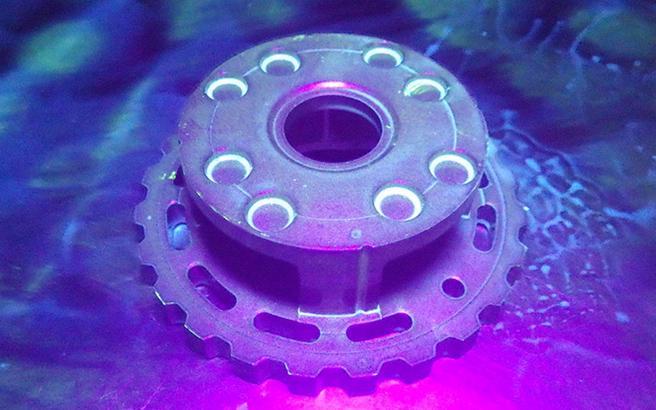
Carriers for planetary gear sets, which are used extensively in automobile transmissions and motor reduction drives, require complex shapes and hollow structures that cannot be formed using tooling alone.
Instead, they are manufactured by joining multiple parts together. Our sinter-brazing joining technology, which joins parts during the sintering process using our own independently developed brazing material, allows us to manufacture such products. Our strengths built up over years of experience with this technology lie in formulating designs that meet our customers’ needs, including but not limited to products with long geometries.
Proposed applications : Carriers for planetary gear sets, long geometries
1. Sintered Part Joining Methods and Characteristics
There are two approaches to joining sintered parts: performing joining and sintering at the same time, or as separate processes. These approaches are further split into different methods, each with its own advantages and disadvantages when it comes to product strength, reliability, material, shape, and cost. Sintered-brazed joints, which we specialize in, have superior strength and reliability, and few restrictions on material and shape.
[++:Superior + : Good - : Satisfactory ×: Inferior] [✔ : Possible]
| Timing | Joining method | Strength | Reliability | Material restrictions | Shape restrictions | Cost | Mass Production | |
| During sintering (Sintering and joining simultaneously) |
Diffusion joining | + | + | - | + | ++ | ✔ | |
| Liquid phase joining | Brazing | ++ | ++ | + | + | + | ✔ | |
| Copper infiltration | + | + | + | + | × | |||
| After sintering (Sintering and joining separately) |
Mechanical joining | Press-fit insertion | - | - | + | + | ++ | ✔ |
| Staking | - | - | - | + | ++ | |||
| Bolts | ++ | ++ | + | - | × | |||
| Liquid phase joining | Welding | + | + | - | + | - | ||
| Cast coating | - | - | + | × | - | ✔ | ||
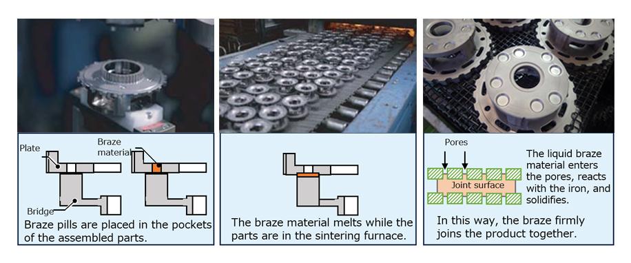
2. Using Sinter-Brazing Technology to Join Carriers
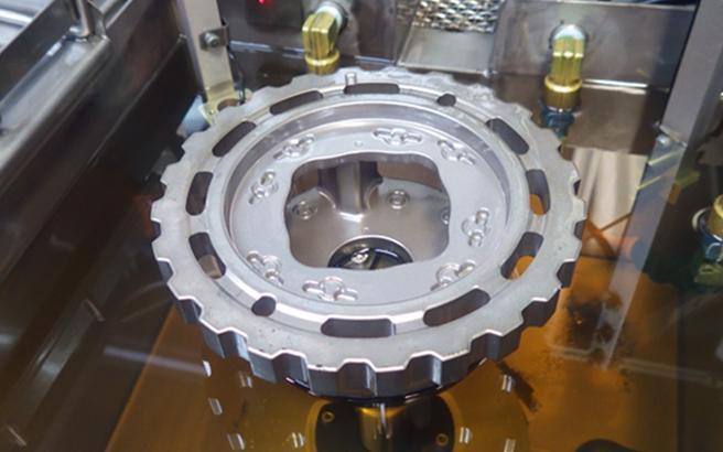
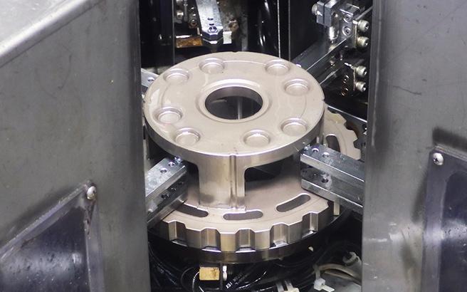
3. In-Process Product Assurance of Sinter-Brazed Carriers
We perform a series of in-line inspections to ensure our carriers are of the highest quality.
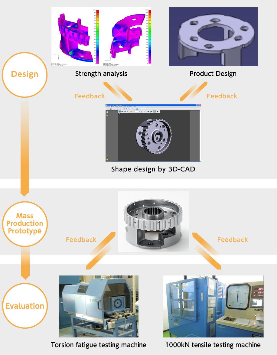
4. Product Development Process
We utilize computer-aided engineering (CAE) when proposing the optimal shapes and process designs to meet our customers’ needs.
Design
We perform CAE analysis based on customer requirements such as torsional torque and thrust force to allow for optimization of column shape, plane of separation, location of braze material pockets, and other design considerations.
Print proposals
Based on the results of the analysis, we propose a print for the product, including material, near net shape (as compacted), plane of separation, area(s) to be machined, and more.
Prototypes (cut samples/off-tool samples)
Cut samples: We machine component parts from sintered blanks, then join them using braze.
Off-tool samples: We create tooling to press green blanks, then join them using braze.
Evaluation
We verify not only the validity of the chosen material through torsional fatigue testing, but also the optimal amount of braze by evaluating the strength of the brazed joint through tensile testing.